Dual Output(s)


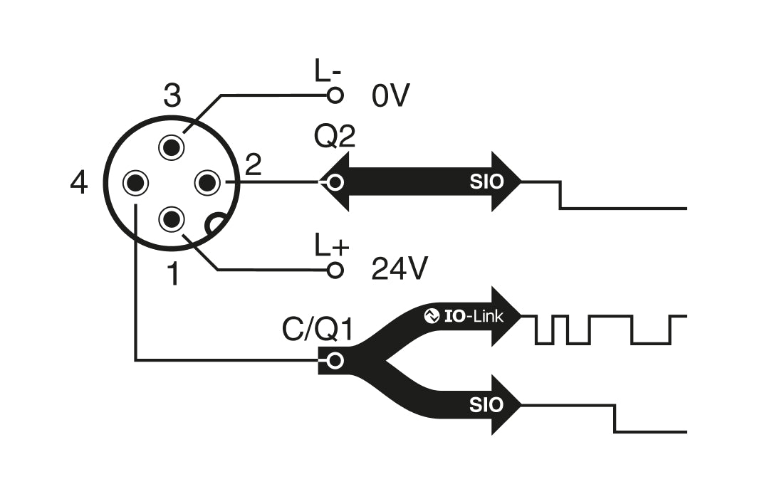
OSS – Output switching signals
OSS1 (Ouput 1) linked to pin/wire number 4. Works as an IO-link pin when connected to an IO-Link master
OSS2 (Output 2) linked to pin/wire number 4. Can also be configured as an SIO Input on DMS Sensors.
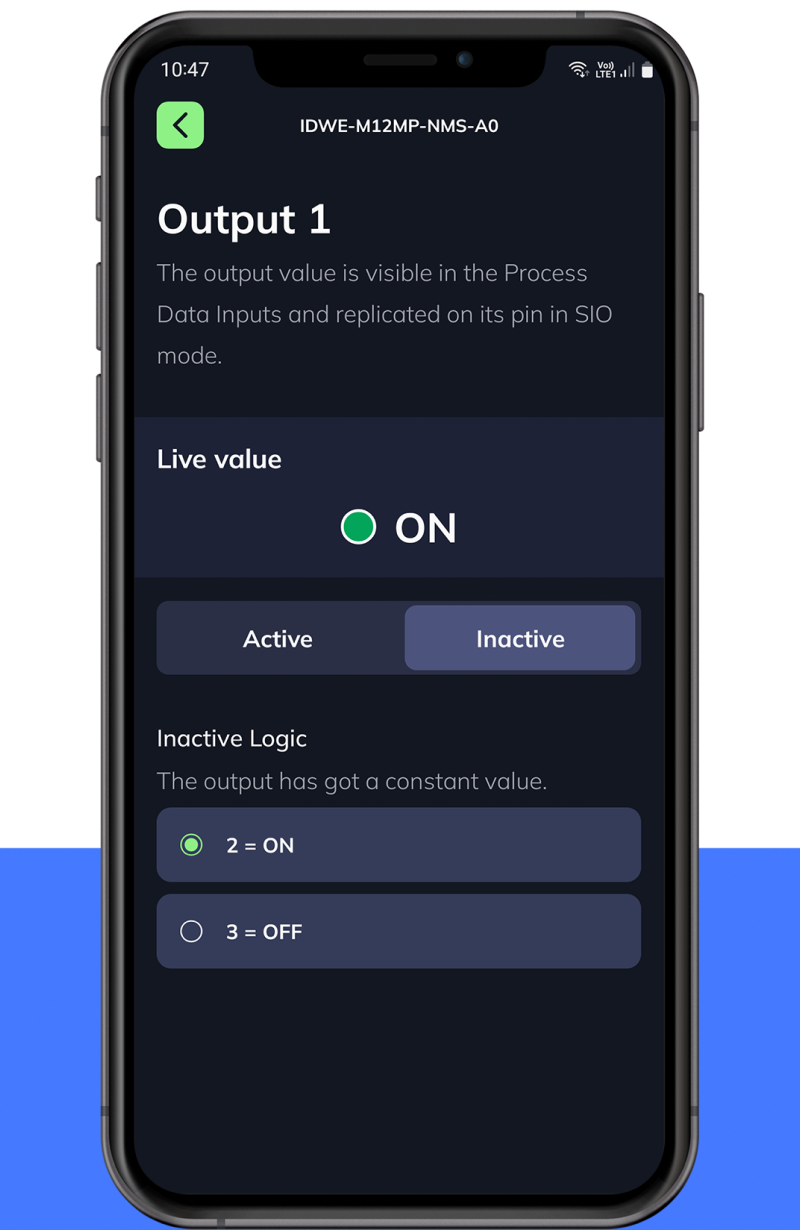
Set Output to Inactive during maintenance and test procedures.
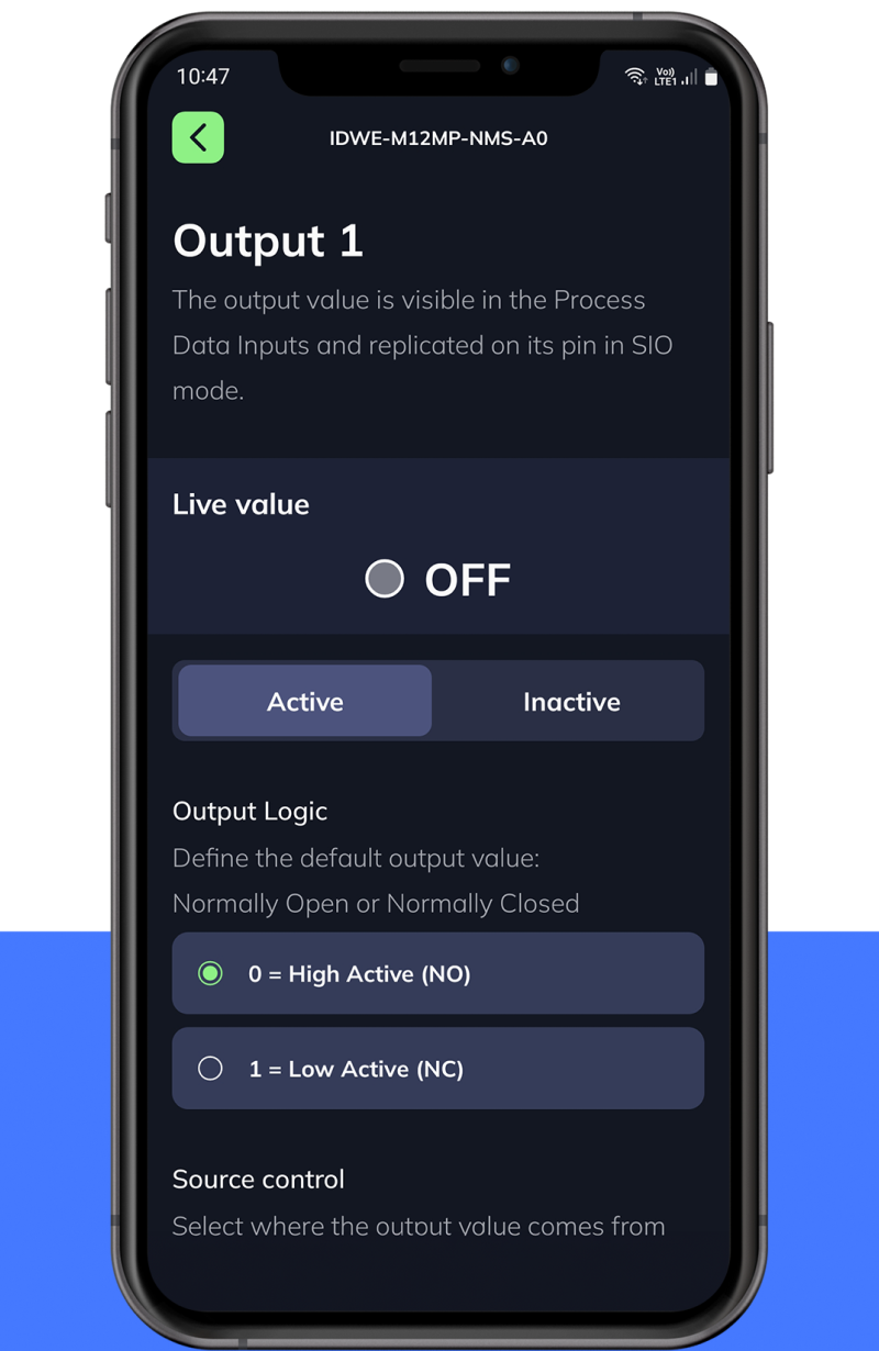
Set Output to Active.
Set output logic to:
High Active (NO) or Low Active (NC)
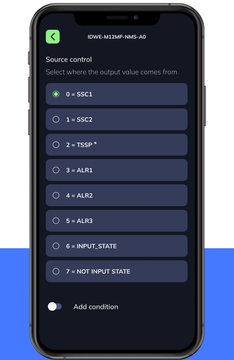
Select internal source signal to be redirected to the output pin.
*Only for Inductive DMS sensors *
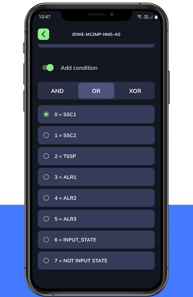
Optionally combine internal signals and alarms and/or an external signal from OSS2 input.
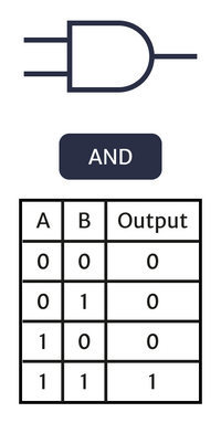
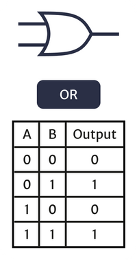
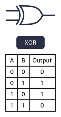
Use AND, OR or XOR functions to define conditional output logic.
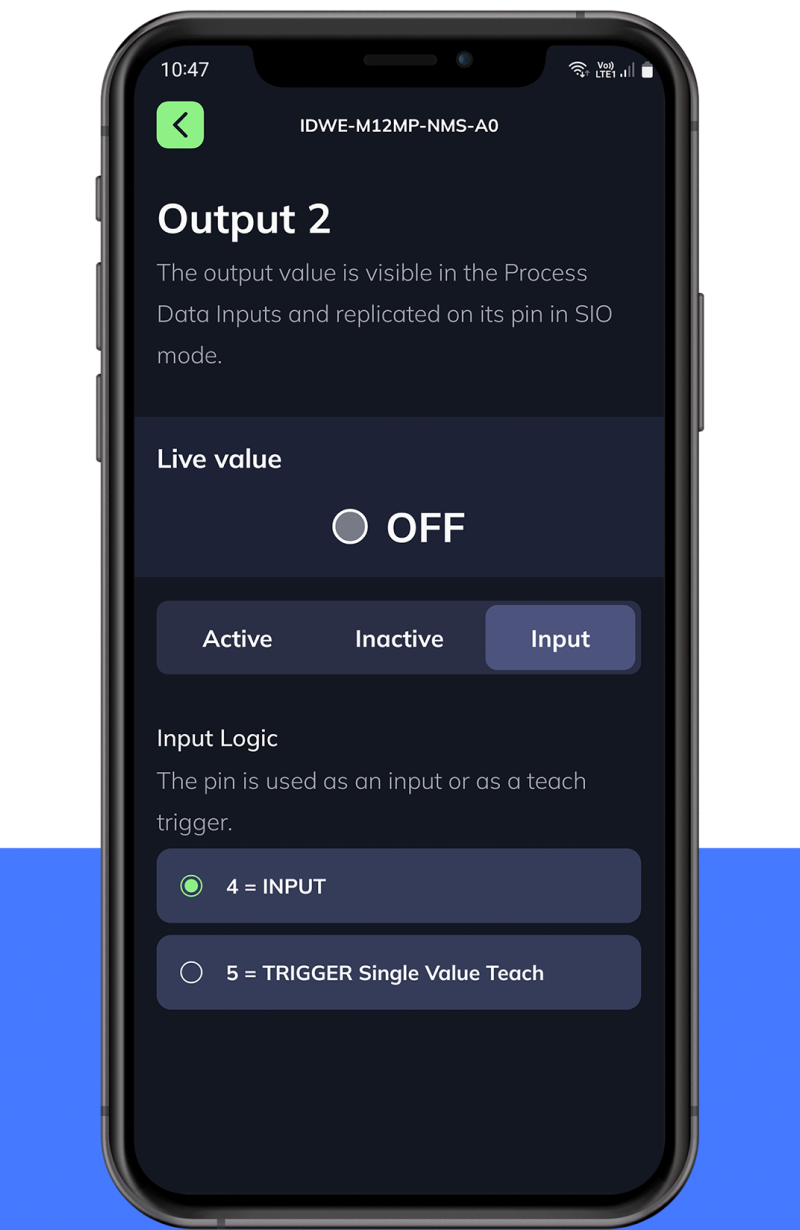
Configure OSS2 (Output 2) as an input signal to be used in logical functions of OSS1 (Output 1).
Useful for daisy chaining of multiple sensors or devices.

Configure Output 2 as an Input to trigger a single value teach on SSC1 (switchpoint 1).